
Guides
General insctructions
The following points must be followed when installing a window:
- All holes are drilled and cleaned before installation.
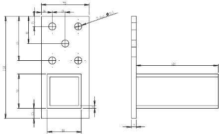
- Window / door mounting brackets are located at distance of 100-150mm from frame inner corner. The distance between the mounting brackets must be <=700mm (Dwg 4.)
- Window / door is placed on supporting blocks that fix it in a horizontal and vertical plane.
- When opening the window / door, the opening will be based first on the leveling and next on the opening dimensions and shape.
- Depending on the foam used, the size of the insulation and the window / door design, place additional supports between the frame and the sash to prevent deformation of the frame by expanding the foam. The supports are released from the warehouse.
- Fill the gap between window / door aperture and frame with mounting foam (eg. Soudal, Penoflex, etc.)
- Protective films on windows / doors should be removed immediately after installation.
- Tips:
- The window / door can be opened 24h after installation.
- Supporting blocks must not be removed.
Add:
Installation aperture preparation:
- The aperture dimension must ensure the possibility of leveling and insulating the element.
- Recommended thickness of insulation sheet min. 10mm.
Door aperture dimensions:
Width = door width + 30mm = door height (with an additional profile!) + 30mm
Assembly
Window mounting brackets or dowels must distribute all forces of the window to the load structure of the building.
Window installation consist of four stages:
- Window cleaning
- Window installation
- Window insulation
- Window finish
Requipments for aperture
The following forces affect the connection between the window and aperture:
Outdoor temperature, rain, wind, noise, sun, construction structure movements.
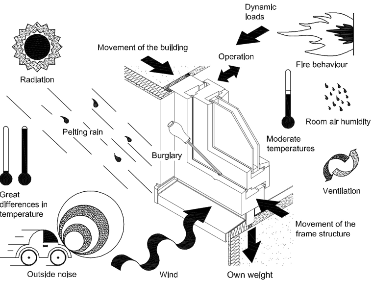
Drawing 1. Window construction deformation
The windows must be levelled in two planes – vertically and horizontally. At the same time, the façade line must also be watched. The window position is fixed with wedges before attaching the window. Tolerances on the dimensions of the window in the building must fit the requirements of DIN 18202. Allowed fluctuations are:
| Window aperture constructional properties | Nominal size up to 2,5 m | Nominal size between 2,5 – 5 m | Nominal size over 5 m |
| Aperture without finish | ± 10 mm | ± 15 mm | ± 20 mm |
| Aperture with finish | ± 10 mm | ± 10 mm | ± 15 mm |
Window ledge and sill installation
The width of the ledge should be chosen so that the nose of the ledge reaches at least 3cm across the façade (water must be directed beyond the surface of the façade when drained) but preferably not more than 6cm (overlap is the risk of winds breaking the ledge). The length of the ledge should be chosen this way, so that even after rolling the ends of the ledge, it is possible to overlap the sheet to prevent water from falling into the edge and between the edges of the ledge. If it is not possible to perform the overlap of the outer sheet on the ledge, the contact surface between the ledge and wall must be sealed. Ledge must be mounted with screws into the additional profile of the window. Additional fastenings to the side or base are optionally carried out according to each specific situation. When installing the ledge, be sure to check that the water level slope is at least 5°
The window sill installation is carried out from the inside against the mounting profile.
The window sills are installed with incline about 2° direct the room, in case of accidental water leak from the outside. The window sill is installed under the window frame towards mounting profile using wedges. In case of long sill, they must be fixed to the upper wedge during assembly, as the window sill may deform when foam is expanding. After supporting the sill, the gap is insulated with foam. The sill is fixed with wedges, foam and the edges are sealed with special covers during the finish works. Additional windows restraints are carried out, if necessary, according to the installation instructions of the window sill manufacturer.
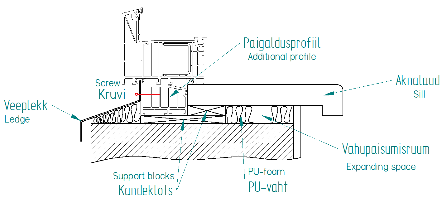
Drawing 2. Ledge and sill installation
NB! When installing water ledges and sills, care must be taken, that the previously made window seals do not break.
Window ledge right installation
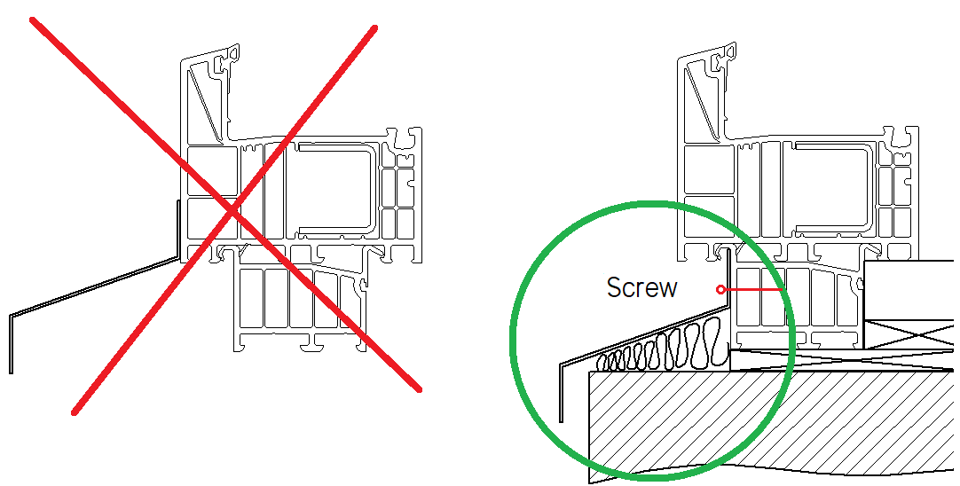
Drawing 3. Ledge installation
| WHITE | COLOR |
| E= frame inner corner – 100-150mm | E= frame inner corner – 150mm |
| Post – 100-150mm | Post – 150mm |
| A = max. 700mm | A = max. 700mm |
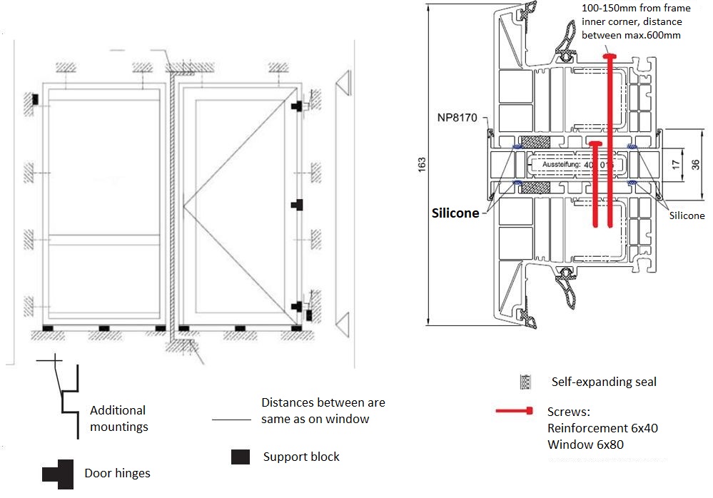
Window mounting brackets installation bE 82 AD and MD
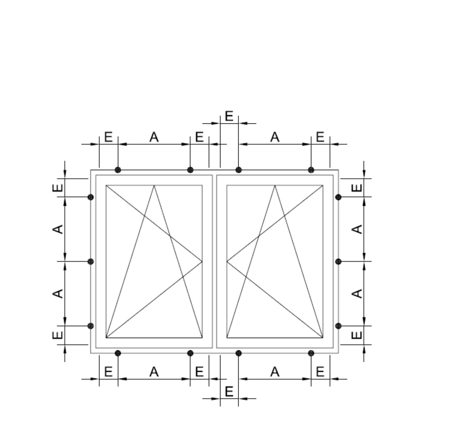
Drawing 4. Mounting brackets positions
Installation blocks positioning
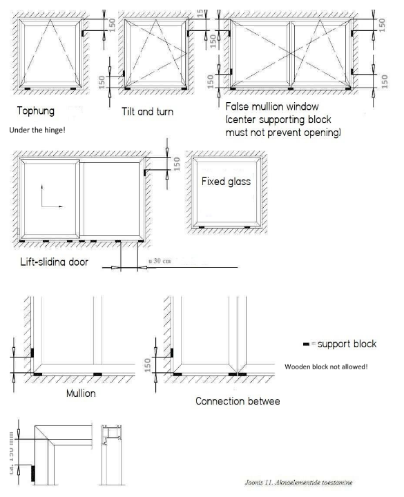
Drawing 5. Installation blocks positioning
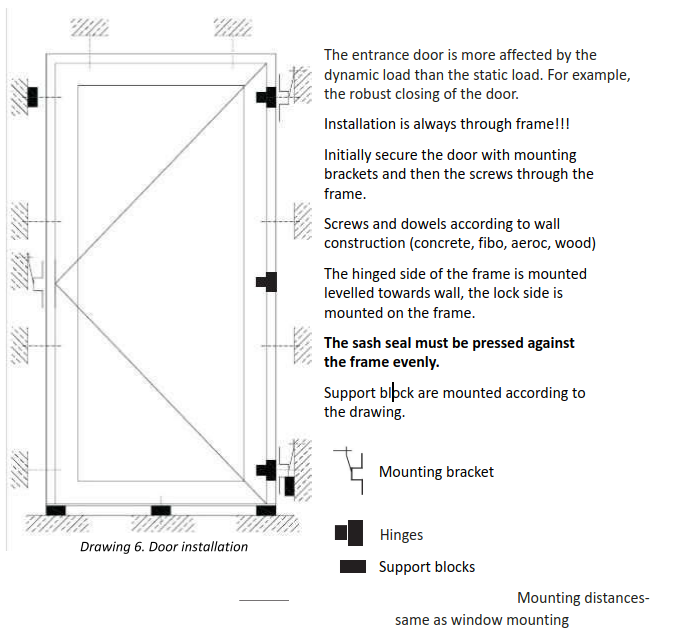
Door intallation (exterior-, sliding-, EvolutionDrive)
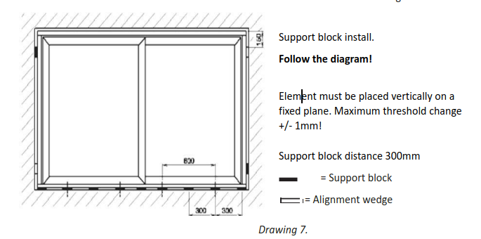
Sliding door installation
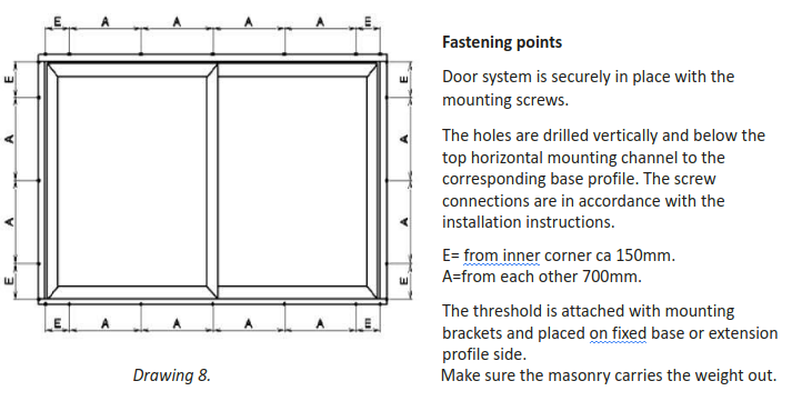
Attach the doors with a screw / dowel through the frame using pre-drilled holes. Install all patio, exterior, folding and sliding doors through the frame.
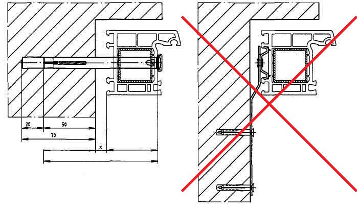
Drawing 9.
Couplings
For safe distribution of forces on the building, the reinforcements must be properly attached. Reinforcements must never be rigidly fixed in such a way, that they can contribute to the movement of the building.
Drawing 10. Drawing.11
NB! Do not remove the support blocks and alignment wedges!
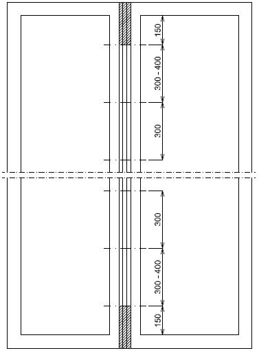
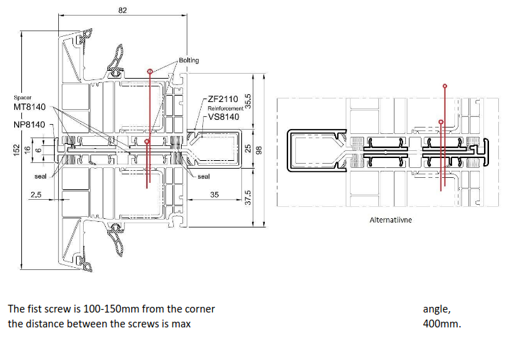
Coupling profile attachment distances
The first screw is 100-150mm from the corner angle, the distance between the screws is max. 400mm.
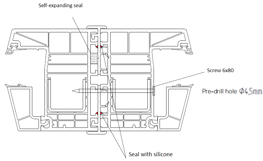
Coupling profile attachment
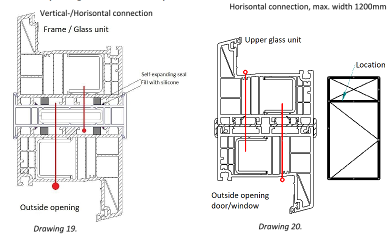
The windows are connected with screws between each other. Self-expanding seal must be fitted between the connections.
Coupling profile with steel reinforcement 82AD/MD
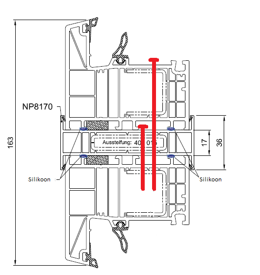
Round- and corner mullion connection
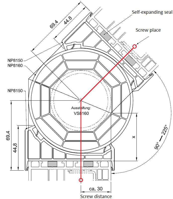
NB! The round mullion is attached to the window with screws. A self-expanding seal is used to connect the mullion and the window.
Horizontal beam connection
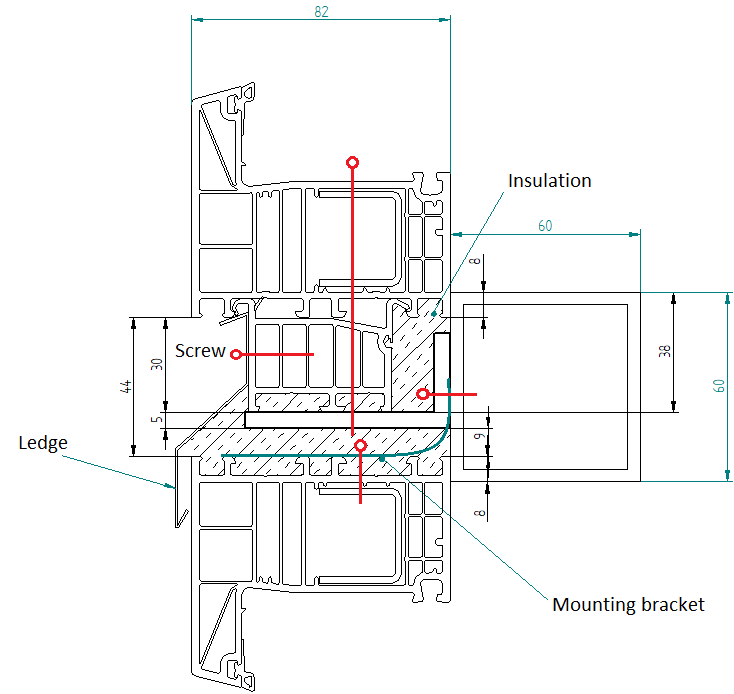
NB! The beam is attached to the wall with metal brackets.
NP8140 Connection with 82AD/MD profile
Outside opening door 82AD/MD profile
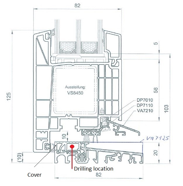
Threshold installation 82AD/MD
Contacts
 Peterburii tee 92D, Tallinn
 www.plasto.ee
 6221 505 (E-R 8.00 - 17.00)